How to make sure that the PCB impedances are correct even after routing changes?
Do you agree that the work of a PCB designer is not always noticeable to others, but very important? The boards you make are built into the latest equipment, often into equipment for responsible use, on which the comfort, health, and sometimes life of people depend. But since these boards are hidden inside the body of the device, no one sees them, and few people remember you – except in those cases when some problems arose precisely because of the printed circuit boards.
The success of your enterprise as a hardware developer and manufacturer, and your personal success as a member of the development team, largely depends on how well you design printed circuit boards. So, in other words: how suitable these boards are for further production (technologically advanced), and how reliable they are in operation (they perform the assigned tasks, so that the device works without failures).
Tracing determines a significant part of your work and result. During the tracing process, you follow predefined rules that are set in the project (or rather, the rules that you have in your head – after all, very often we are too lazy to enter all the rules in CAD, or simply do not have the opportunity to do this). Unfortunately, not everything can be determined by the rules, and not all errors and inaccuracies in the project can be prevented by following the rules. Moreover, not all errors can be visually detected, and even with the help of existing PCB CAD systems, not all can be seen. For example, how do you find locations where the impedance of a critical conductor deviated from the nominal value due to the fact that during the design adjustment, this conductor passed over a break in the earth polygon? Or – how to detect that two critical conductors situated next to each other so close and so long that the crosstalk between them exceeds the permissible level?
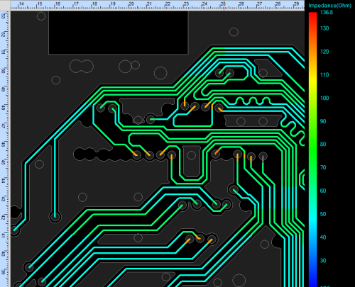
Modern CAD PCBs are there to help, they can visually display the real impedance of the conductor that will be on the board, and, of course, issue an appropriate report for easy viewing and finding problem areas. In Cadence OrCAD (a subset of Allegro), this impedance control is done using Sigrity modeling technologies built right into the OrCAD PCB Designer editor.
You are not working in OrCAD, but in other design systems? Well, then you can, for example, import your project from P-CAD into OrCAD (our company has such translator, which quite well allows you to draw the trace from P-CAD 2004/2006 and analyze it in OrCAD, or even correct and reroute some chains and polygons directly in the OrCAD editor). Then you need to set the structure of the board layers (this is an elementary operation, specify the permittivity and dielectric thickness in the layer table), and launch the menu item Analyze – Workflow manager, select the desired layer, specify critical circuits (for example, OUT, if we are interested in circuits, that have OUT in their name) and run the impedance analysis.
Just turn on the Impedance Vision mode and see the result – right in the PCB Editor, you can see a graphical scale that displays the real impedance throughout the entire length of each critical conductor. You can click on the areas of interest to us and figure out what is the reason for the deviation, and immediately correct the tracing by correcting project errors on quick. It is possible to select on the scale only the range of wave impedances that interests us, and all other sections of the conductors will be darkened. Both single and differential impedance can be analyzed.

If it is necessary, you can also view crosstalk – in the same Workflow manager, you need to select Coupling Workflow, and the system will immediately show you which of your critical circuits are at risk of excessive interference that can disrupt the performance of your electronics.
Do you want to try? There is nothing easier – you can download the Trial version of OrCAD Professional CAD for 30 days from orcad.com, section TRIAL.
It would be glad to see your comments here – Has this feature helped you personally, or have you considered it useless in your work?